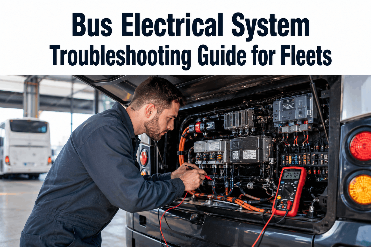
Electrical problems are among the most frustrating issues fleet managers face. A bus mysteriously loses power, won't start, or shuts down mid-route. Diagnosing these electrical glitches is challenging because symptoms rarely point directly to the root cause. Without a methodical approach, a technician might spend hours swapping out perfectly good parts. Modern buses with CAN-bus networks add even more complexity, where a fault in one module can trigger failures across seemingly unrelated systems. Understanding electrical system basics and leveraging a digital system like BusCMMS helps teams troubleshoot methodically, track recurring fault codes, and eliminate costly guessing games. Here's a comprehensive guide to bus electrical system troubleshooting.
Symptom: Bus won't start or starts slowly. First step is testing the battery. A good battery provides 12-13 volts at rest and 13.5-14.5 volts while running. Use a voltmeter to measure voltage at battery terminals. If voltage is below 12 volts, the battery is weak or discharged. If voltage is normal at rest but drops to near zero when cranking, battery capacity is inadequate. Keeping track of battery age and testing histories inside BusCMMS helps fleets replace aging units before winter weather hits.
Battery connections are critical. Corroded terminals (white, blue, or green crusty buildup) increase electrical resistance and reduce current flow. Clean terminals by disconnecting the battery, scrubbing terminals and cable ends with a wire brush, and reconnecting. Apply dielectric grease to terminals to prevent future corrosion. Loose connections create high resistance and voltage drops; connections should be tight enough that the cable doesn't move when pulled.
Parasitic battery drain occurs when electrical systems draw current even when the bus is off. A healthy bus should draw less than 100 mA when off. Drains exceeding 500 mA indicate a problem. To measure parasitic drain, disconnect the negative battery terminal, connect an ammeter in series, and measure current. If current is high, pull fuses one at a time to isolate the faulty circuit. Common culprits include stuck relays, faulty aftermarket equipment, or modules that fail to enter sleep mode.
Symptom: Charging system warning light on, or battery drains during operation. The alternator maintains battery voltage while running and should produce 13.5-14.5 volts under load. If voltage is lower, the alternator isn't producing adequate output. Common causes include a loose alternator belt, failed internal brushes, or a faulty voltage regulator. Setting up automated Preventive Maintenance (PM) schedules in your fleet software ensures belt tension and alternator health are checked during routine inspections.
Check alternator belt first. The belt should be tight with about 1/2 inch of deflection when pressed. Missing chunks or a glazed surface indicates replacement is needed. If the belt is tight and output is still low, perform an ammeter test to check current capacity. A failing alternator might produce acceptable voltage at rest but completely fail to deliver the necessary current under full electrical load.
Modern buses utilize integrated voltage regulators inside the alternator assembly. A faulty regulator might produce excessive voltage (15+V), which risks cooking the batteries and damaging sensitive onboard electronic modules. Because testing internal regulators requires specialized bench equipment, operators typically track these asset replacements as complete units within their inventory management system.
Symptom: One or more lights don't work. Single light failures are usually straightforward: a burnt bulb, loose connector, or corroded socket. Test the circuit by swapping in a known good bulb. If the light still doesn't function, check for voltage and ground at the socket itself. Corroded pins should be cleaned and protected with dielectric grease.
Multiple light failures point toward a shared circuit issue or a bad ground. If an entire bank of marker lights or brake lights fails simultaneously, check the shared chassis ground connection. A corroded ground increases resistance, causing erratic light behavior or dimming when other heavy electrical loads (like heater fans or wheelchair lifts) kick on. Logging these recurring defects in a central CMMS helps fleet managers identify systemic wiring defects across specific vehicle models.
Modern buses rely on CAN-bus (Controller Area Network) architectures where multiple electronic control units (ECUs) communicate over a shared data network. A single network failure can spark a cascade of symptoms: multiple dash warning lights, intermittent starting issues, or mysterious transmission shifts. Technicians must utilize an OBD-II or J1939 diagnostic scanner to pull network communication codes.
CAN-bus wiring consists of a tightly twisted pair of wires designed to cancel out electromagnetic interference from the engine and alternator. Physical damage, wire rubbing, or moisture intrusion will disrupt data packets. If network diagnostics reveal poor signal quality, technicians should verify the status of the 120-ohm termination resistors located at the physical ends of the bus network. When these communication faults are documented inside a digital work order system, shop foremen can track chronic module errors and coordinate specialized programming support when needed.
Voltmeter: Essential for checking electrical potential. Measure battery voltage at rest (12-13V) and while running (13.5-14.5V) to immediately isolate charging versus storage faults.
Ammeter: Used for testing circuit current draw. Crucial for measuring total alternator output under full accessory load and pinpointing tricky parasitic drains when the vehicle is turned off.
Ohmmeter: Measures electrical resistance. Ideal for checking wire continuity, assessing switch states, and confirming that ground connections read close to zero ohms.
OBD-II / Heavy-Duty Scanner: Reads diagnostic trouble codes (DTCs) from the bus's onboard computers. Vital for identifying which modules are dropping offline on modern multiplexed networks.