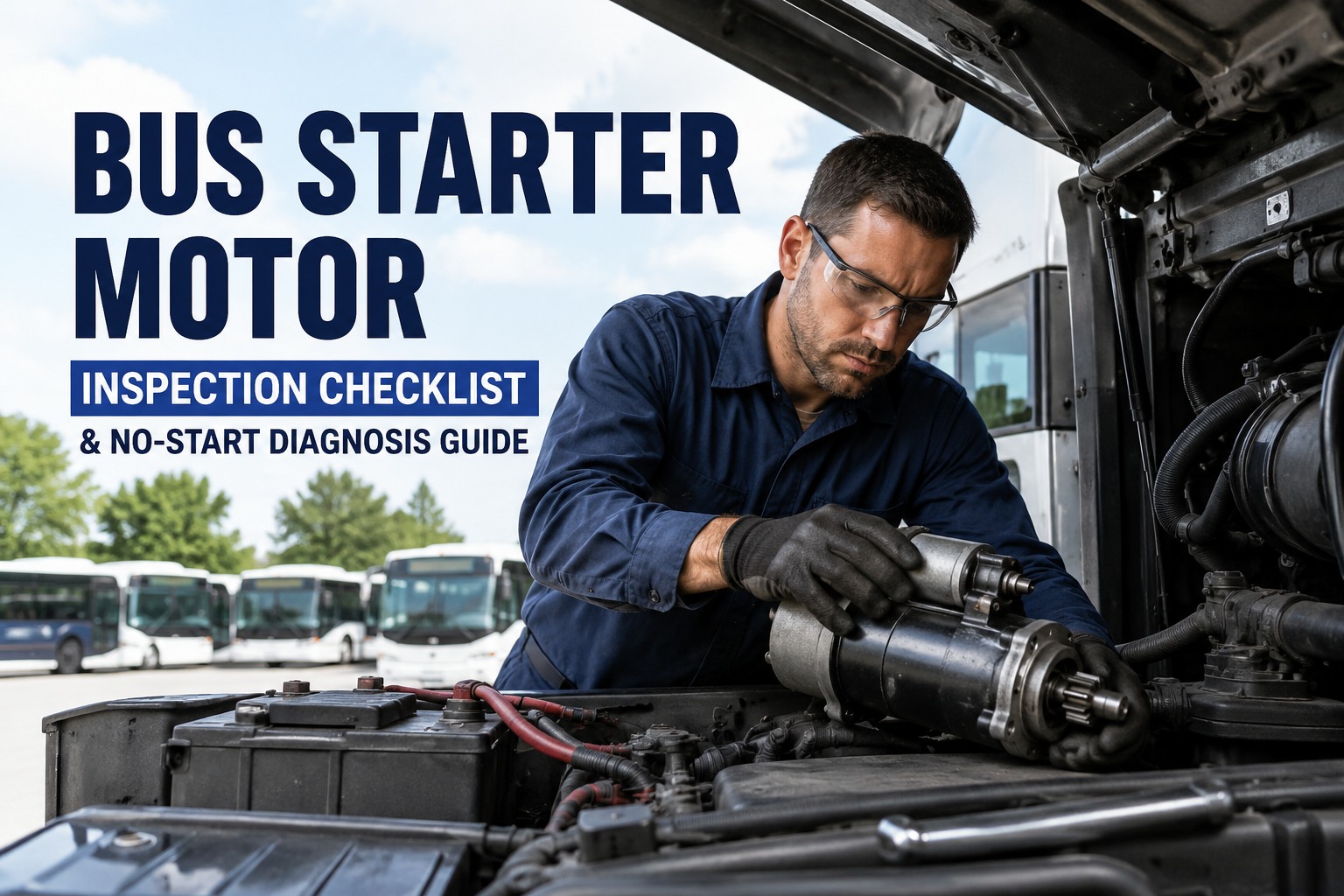
Your driver turns the key at 6:12 AM and gets one hard click, then silence. The bus is dead in the yard, the AM route is 47 minutes from departure, and every minute after 6:45 is a phone call to a parent explaining why their kid is standing at the bus stop in the cold. No-start events are one of the most disruptive maintenance failures in bus fleet operations, and 80% of them trace to the starter system. This checklist covers the amp draw, cranking voltage, voltage drop, solenoid, and ring gear tests that catch starter failures before the driver turns the key.
Bus Starter Motor Inspection Checklist & No-Start Diagnosis Guide
The complete field test procedure for bus starter motors -- amp draw testing, cranking voltage, voltage drop measurement, solenoid operation, brush wear, ring gear inspection, and the no-start diagnostic flow that gets the bus back in service before AM pull-out.
The Real Cost of an AM Pull-Out No-Start
A starter failure at 6:12 AM is not just a maintenance issue. It cascades into missed routes, parent calls, driver overtime, and towing bills.
Starter replacement
New OE heavy-duty starter for a diesel bus, plus 1.5-3 hours of labor. Reman starters run $250-$650 for the same fitment.
Substitute bus scramble
Every no-start at pull-out means finding a spare, dispatching a substitute driver, and calling parents. Compounds across every stop.
Emergency tow cost
If the bus fails on route, tow cost adds to the repair bill. Multiple tows over a year add up faster than proactive replacement.
Preventable failures
Roughly 80% of no-start events show warning signs on the previous PM cycle -- slow crank, dim dash lights, marginal amp draw. Test catches them.
Book a demo to see how BusCMMS surfaces trending starter weakness before it becomes a no-start.
6 Components in the Starter Circuit
Every no-start diagnosis follows the same six-component circuit. Test each in sequence, from the battery back to the ring gear.
Batteries + Cables
Series-connected 12V batteries feeding the starter. Cables must be corrosion-free with clean, tight terminals at both ends.
Ignition Switch Circuit
Low-amperage signal path from the key switch through the neutral safety switch to the starter solenoid coil.
Starter Solenoid
Electromagnetic switch that closes the high-amperage circuit to the starter motor and pushes the drive gear into the ring gear.
Starter Motor + Brushes
DC motor with commutator and brushes. Brushes wear over time and eventually lose contact pressure, causing weak or intermittent crank.
Bendix Drive Gear
Pinion gear that extends to mesh with the ring gear, then retracts after engine start. Wear or damage causes grinding or slippage.
Flywheel Ring Gear
Toothed ring mounted on the flywheel that the drive gear engages. Missing teeth cause skip or grind at cranking.
Complete Starter Motor Inspection Checklist
Organized by test type. Each item shows the Test method, target Specification, and Diagnosis if it fails.
Pre-Crank Visual Inspection
-
A1 · Battery terminals + cables
Test
Visually inspect both terminals and cable connections. Look for corrosion, loose clamps, and cable insulation damage.
SpecClean terminals, tight clamps (no movement), no green/white corrosion buildup, intact insulation full cable length.
DiagnosisCorrosion = high resistance = weak crank. Loose clamp = voltage drop. Damaged insulation = intermittent short.
-
A2 · Starter housing + mount
Test
Inspect starter body for oil leaks around end housing, damage, and secure mounting bolts.
SpecDry housing, no oil residue, mounting bolts tight to spec (typically 30-50 ft-lb depending on OEM).
DiagnosisOil at housing = failed seal, contamination of brushes. Loose mount = misalignment with ring gear.
-
A3 · Wiring harness + solenoid connections
Test
Inspect solenoid terminal connections and starter wiring harness for burnt insulation and secure fit.
SpecAll connections tight, no discoloration or melted insulation, harness properly routed away from exhaust heat.
DiagnosisBurnt insulation = high current + resistance. Loose connection = intermittent no-start.
Amp Draw Testing
-
B1 · Cranking amp draw measurement
Test
Attach inductive amp clamp around the positive battery cable. Crank engine (fuel disabled) for 5-10 seconds. Note peak amp reading.
SpecDiesel bus starter typically draws 300-600 amps during normal cranking. Consult OEM spec for exact vehicle.
DiagnosisAbove 600A = starter drag, worn bushings, or seized engine. Below 300A = worn brushes, weak solenoid, or open winding.
-
B2 · Cranking duration + heat
Test
Observe how long the starter cranks before engine start (or 15-second test limit). Feel starter housing after cool-down.
SpecNormal cold start: 2-5 seconds of cranking. Warm start: 1-3 seconds. Housing warm but not hot after cool-down.
DiagnosisExtended cranking + hot housing = starter overworking, likely brush wear or armature drag. Rest 2 minutes between cranks to avoid damage.
Cranking Voltage + Voltage Drop Testing
-
C1 · Cranking voltage at battery
Test
Attach voltmeter to battery posts. Crank engine and read lowest voltage during cranking.
SpecMinimum 9.6V under cranking load. Below this indicates battery weakness or excessive current draw.
DiagnosisBelow 9.6V with healthy battery = starter drawing too much amp. Below 9.0V = replace battery, then re-test starter.
-
C2 · Positive cable voltage drop
Test
Voltmeter black lead on battery positive post, red lead on starter solenoid battery terminal. Crank and read voltage.
SpecBelow 0.5V drop during cranking. Ideal is under 0.3V.
DiagnosisAbove 0.5V = corroded cable, loose connection, or undersized cable. Clean, tighten, or replace cable.
-
C3 · Ground cable voltage drop
Test
Voltmeter red lead on battery ground post, black lead on starter mount (bare metal). Crank and read voltage.
SpecBelow 0.2V drop during cranking. Ideal is under 0.1V.
DiagnosisAbove 0.2V = poor ground path, paint or corrosion at mount, loose ground strap. Bad grounds cause the majority of no-starts.
-
C4 · Solenoid switch voltage drop
Test
Voltmeter across solenoid battery terminal and starter motor terminal. Crank and read voltage.
SpecBelow 0.2V drop across the closed solenoid contacts during cranking.
DiagnosisAbove 0.2V = burned or pitted solenoid contacts. Solenoid is on its way out even if starter still cranks.
Solenoid + Ring Gear Inspection
-
D1 · Solenoid engagement click test
Test
Turn key to start. Listen for a distinct solenoid click at engagement (or ask helper while you listen at the starter).
SpecOne clean, distinct click at key-on. No delay, no repeated clicks, no chatter.
DiagnosisRapid chatter clicks = low battery or high resistance. No click = failed solenoid or open control circuit. Delayed click = weakening solenoid coil.
-
D2 · Drive gear engagement + retract
Test
Bump-crank the starter with cover removed (safety per OEM). Verify drive gear extends, engages, and retracts cleanly after crank.
SpecClean extend + retract action. No hang-up, no premature disengagement, no grinding during retract.
DiagnosisHang-up = bendix drive worn or dirty. Grinding = drive gear or ring gear damage. Fails to engage = solenoid plunger weak.
-
D3 · Ring gear tooth inspection
Test
Rotate engine by hand (turn crank pulley by wrench). Visually inspect every ring gear tooth through the starter port.
SpecAll teeth present, no chips, no rounded tips, even wear pattern around the full gear.
DiagnosisMissing teeth = ring gear replacement (major job). Rounded tips = worn drive gear also. Uneven wear = starter misalignment.
No-Start Symptom Diagnosis: What the Sound Tells You
The first thing a bus mechanic listens for when a driver reports "it won't start" is the sound at the key. Each pattern points to a different diagnostic path.
Single click, no crank
Most likely: Solenoid engaged but no current to motor. Bad connection, burnt solenoid contacts, or seized starter.
Voltage drop across solenoid contacts. Above 0.2V = solenoid failing. Also check ground path.
Rapid clicking, no crank
Most likely: Low battery voltage collapsing under solenoid load. Solenoid pulls in, voltage drops, releases, cycles.
Battery voltage under load. Below 9.6V during crank attempt = weak battery. Load-test each battery individually.
Slow crank, engine turns
Most likely: High resistance in starter circuit or worn starter brushes. Amp draw will read high.
Amp draw test. Above OEM spec = brush wear or armature drag. Voltage drop tests to locate resistance.
Grinding at start
Most likely: Drive gear or ring gear tooth damage. Starter tries to engage but teeth do not mesh correctly.
Visual inspection of ring gear through starter port. Rotate engine by hand to check every tooth.
Nothing at key (silent)
Most likely: No power to solenoid coil. Ignition switch, neutral safety switch, or control circuit open.
Test voltage at solenoid S-terminal during key crank. No voltage = trace control circuit backward from solenoid.
Starter keeps running after key release
Most likely: Solenoid contacts welded shut, or stuck plunger. Disconnect battery immediately to prevent damage.
Replace solenoid immediately. Do not attempt to keep bus in service until fixed -- ring gear damage compounds fast.
Book a demo to see how BusCMMS logs no-start events + diagnostic outcomes per bus.
Common Starter Failures + Fixes
Six failure patterns account for the majority of starter-related no-starts in bus fleets. Recognize the pattern, apply the fix.
Worn brushes
The most common starter failure. Brushes wear from repeated cranking and lose contact pressure. Rebuild kit or reman starter replacement.
Failed solenoid
Contacts pit and burn from arcing at engagement. Solenoid replacement (often available separately from the starter motor).
Corroded battery cables
Green/white corrosion under cable connector or inside cable end. Clean or replace cable, retreat with anti-corrosion compound.
Bad ground
Paint or corrosion at starter mount, loose ground strap, or aged main ground cable. Clean the mount surface, replace strap if needed.
Slipping bendix drive
Drive spring wear allows the gear to slip instead of turn the engine. Replace bendix assembly or the whole starter.
Ring gear damage
Missing or rounded teeth from mis-engagement (often traces to failed starter that was ignored). Ring gear replacement is a transmission-drop job.
Book a demo to see how BusCMMS tracks starter replacement history + parts cost per bus.
Turning the Checklist Into No-Start Prevention
Marginal starter test results on Bus 24 today become a no-start on Bus 24 two weeks from now. Digital DVIRs capture the trend line early enough to act.
Bus-specific starter test items
Amp draw, cranking voltage, and voltage drop tests pre-loaded into the digital DVIR alongside other bus-specific inspection points. Technician sees the correct starter test sequence for every bus type.
Test results logged per bus
Every amp draw and voltage reading captured per bus, per test date. Trending data surfaces starters that are drifting toward failure before the driver reports a slow crank.
Auto-generated work orders
A failed starter test item automatically creates a work order for replacement or rebuild. Parts, labor, and material cost tracked against that bus.
No-start event history
Every no-start event logged with root cause, repair action, and cost. Fleet-wide reports surface the buses with recurring starter issues for proactive replacement.
Five minutes with the amp clamp and voltmeter on the shop floor prevents 45 minutes of driver overtime and parent phone calls on the yard. Book a demo to see the starter test tracking + no-start prevention workflow live.
What is the normal amp draw for a bus starter motor?
Heavy-duty diesel bus starters typically draw 300-600 amps during normal cranking, depending on engine displacement, temperature, and starter design. Consult the specific OEM specification for exact target values. Amp draw above the spec range indicates starter drag, worn bushings, or engine internal resistance. Amp draw below the spec range typically indicates worn starter brushes, weak solenoid engagement, or an open winding in the armature.
What is the minimum cranking voltage for a bus?
Minimum acceptable cranking voltage measured at the battery posts is 9.6V during starter engagement. This assumes a healthy 12V battery system (or the equivalent point on 24V systems). Below 9.6V indicates either battery weakness or excessive current draw from a starter drawing more than spec. Below 9.0V during cranking, replace the battery first and re-test the starter with the new battery.
What voltage drop is acceptable across starter cables?
Positive cable voltage drop should stay below 0.5V during cranking, with ideal readings below 0.3V. Ground cable voltage drop should stay below 0.2V (ideal below 0.1V). Solenoid contact voltage drop should stay below 0.2V. Bad grounds are the single most common cause of no-starts that get misdiagnosed as bad starters -- always test the ground path before condemning the starter itself.
Can I rebuild a heavy-duty bus starter or should I replace it?
Both are viable. OE-quality reman starters run $250-$650 for typical bus fitments and carry 12-18 month unlimited-mile warranty from reputable suppliers. New OE starters run $400-$1,200. In-house rebuild kits (brushes, solenoid, drive) run $80-$200 but take 2-4 hours of tech time. For fleets with in-house electrical capability, rebuild kits work for lower-hour starters. For high-utilization buses, reman replacement is usually faster and comes with warranty.
How does BusCMMS help prevent no-start failures?
BusCMMS captures starter test results (amp draw, cranking voltage, voltage drop readings) per bus, per PM date in the digital DVIR. Trending readings that drift toward failure spec surface in fleet reports before the starter actually fails on the driver at 6:12 AM. Failed test items automatically generate work orders for repair or replacement. No-start event history logged per bus lets fleet managers identify buses with recurring starter issues for proactive replacement rather than reactive tows. Book a 20-minute demo to see the workflow live, or start a 30-day free trial.