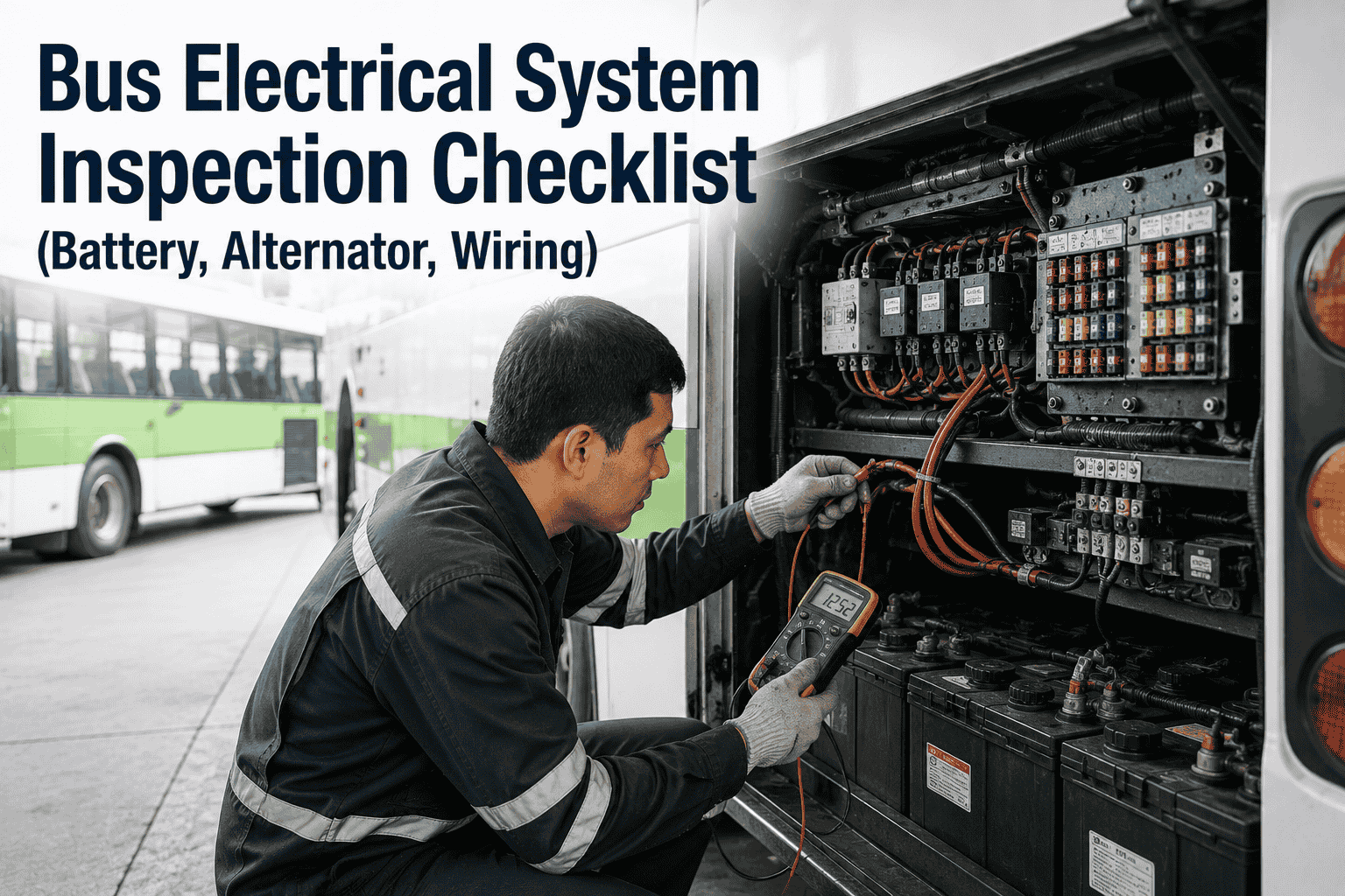
Electrical system failures are among the most frustrating and difficult-to-diagnose issues in bus fleet maintenance. A single faulty ground point can cause intermittent starting problems, flickering lights, and erratic gauge readings that drive technicians to replace parts unnecessarily. Battery failures leave buses stranded at the depot. Alternator failures cause breakdowns on route. Wiring harness damage can create intermittent faults that are almost impossible to trace without a systematic inspection process. This comprehensive bus electrical system inspection checklist covers battery condition testing, alternator output verification, voltage regulator function, wiring harness inspection, fuses and relays, and ground point verification. Use it as your standard procedure for every electrical system PM and diagnostic inspection.
Electrical System Guide 2026
Bus Electrical System Inspection Checklist (Battery, Alternator, Wiring)
Bus electrical system inspection workflow. Battery condition, alternator output, voltage regulator, wiring harness, fuses, relays and ground points.
Why Electrical Inspections Are Critical: The Hidden Failure Points
Electrical system failures account for approximately 15-20% of all bus breakdowns and service disruptions. Unlike mechanical failures that often show warning signs, electrical failures can be sudden and catastrophic—a dead battery at the depot, an alternator failure on the highway, or a wiring short that disables the entire bus. The most common electrical failures include: battery failure (sulfation, internal short, low electrolyte), alternator failure (worn brushes, failed diodes, bearing failure), voltage regulator failure (overcharging or undercharging), and wiring harness damage (chafed, corroded, or broken wires).
The financial impact of electrical failures is significant. A single roadside alternator failure can cost $1,500–$2,800 in repairs plus towing and route disruption. Battery failures cost $300–$600 per replacement plus service disruption. Wiring harness repairs can cost $800–$3,500 depending on the extent of damage. A structured electrical inspection process is the most effective way to prevent these outcomes and ensure fleet reliability.
Electrical System Inspection Categories: The Complete Checklist
This comprehensive electrical inspection checklist covers every major electrical component. Use it during every electrical PM service, pre-trip inspection, and annual DOT inspection.
Voltage Drop Testing: The Most Overlooked Diagnostic
Voltage drop testing is the single most effective diagnostic technique for identifying electrical system problems. A voltage drop of 0.5V or more in a circuit indicates resistance that will cause poor performance or failure. Most technicians skip this test, but it identifies issues that visual inspection alone cannot detect.
Battery Positive Circuit
Measure voltage drop from battery positive terminal to the starter positive terminal. Acceptable: 0.1–0.3V. High reading indicates corroded or loose connections.
Battery Negative Circuit
Measure voltage drop from battery negative terminal to engine block. Acceptable: 0.1–0.2V. High reading indicates poor ground connection.
Alternator Output Circuit
Measure voltage drop from alternator output to battery positive. Acceptable: 0.1–0.3V. High reading indicates damaged or undersized wiring.
Starter Circuit
Measure voltage drop across starter during cranking. Acceptable: 0.2–0.4V. High reading indicates poor connections or undersized cables.
Battery Testing: Load Test vs. Conductance Test
Battery testing is the foundation of electrical system reliability. A battery that tests below 80% capacity should be replaced immediately to prevent starting failures. Load testing remains the industry standard, but conductance testing provides faster results with similar accuracy. The most reliable approach uses multiple testing methods combined with visual inspection.
Common Electrical Failure Patterns and Root Causes
Understanding common electrical failure patterns helps technicians diagnose problems faster and prevent recurring issues.
Intermittent Starting
Cause: Corroded battery connections, failing starter, or poor ground. Fix: Clean all connections, test starter circuit voltage drop. Often misdiagnosed as bad starter.
Flickering Lights
Cause: Loose alternator belt, failing voltage regulator, or intermittent ground. Fix: Test alternator output, inspect belt tension, clean ground points.
Dead Battery Overnight
Cause: Parasitic draw from failed component or leaving lights on. Fix: Perform parasitic draw test. Identify and repair leaking component.
Erratic Gauges
Cause: Poor ground connection at instrument cluster or faulty sensor. Fix: Clean instrument cluster ground. Test sensor output.
No Start Condition
Cause: Dead battery, failed alternator, faulty starter, or safety interlock failure. Fix: Systematically test each component in sequence.
Charging System Warning
Cause: Failed alternator, broken belt, or voltage regulator failure. Fix: Test alternator output. Inspect belt. Verify regulator function.
We implemented this electrical inspection checklist across our 95-bus fleet after a series of battery failures and alternator breakdowns. In the first six months, we caught 23 batteries that tested below 80% capacity before they failed on route. We identified 8 alternators with failing diodes before they left buses stranded. The checklist gives our technicians a systematic process for electrical diagnosis, and our electrical-related breakdowns dropped by 67% in year one.
Digitize Your Electrical System Inspection Process
BusCMMS guides technicians through every electrical inspection point—battery testing, alternator output verification, voltage drop measurement, wiring inspection, and ground point verification. Auto-schedule electrical PM intervals based on mileage. Complete audit trail for every electrical component in your fleet.
Bus Electrical System FAQs
What is the normal alternator output voltage for a bus?
For 12V bus electrical systems, normal alternator output is 13.5–14.5V at idle and 1,500 RPM. For 24V systems, normal output is 27.0–29.0V. Output below specification indicates alternator or voltage regulator issues. Output above specification can damage batteries and electrical components.
How often should bus batteries be tested?
Bus batteries should be tested at every preventive maintenance service (typically every 15,000–20,000 miles or 6 months). Load testing is recommended in spring and fall to catch batteries that may fail in extreme temperatures. Any battery below 80% capacity should be replaced immediately.
What are the signs of a failing alternator?
Warning signs include: dim or flickering headlights, slow electrical accessories, dashboard warning light illuminated, battery not charging properly, unusual noise (whining or grinding) from alternator, and frequent battery drain. Regular alternator output testing catches these issues early.
How do I find a parasitic draw on a bus?
Use a DC ammeter between the battery negative terminal and cable. Normal parasitic draw for a modern bus is 50–100mA. Draw above 100mA indicates a failed component. Isolate by removing fuses one at a time until the draw drops—the last fuse identifies the circuit with the fault.
Why are ground points so important for bus electrical systems?
Poor ground points are the #1 cause of intermittent electrical issues on buses. A single corroded ground can cause flickering lights, erratic gauges, slow starting, and charging system problems. Regular ground point inspection, cleaning, and torquing prevents these issues.
Can BusCMMS track electrical system inspection history?
Yes. BusCMMS tracks battery test results, alternator output readings, voltage drop measurements, and all electrical inspection findings. This creates a complete electrical system history for each bus, helping identify recurring issues and predict component failure.
The Bottom Line
Bus electrical system inspections are critical to fleet reliability and uptime. Battery failure, alternator breakdowns, and wiring issues are among the most common causes of roadside breakdowns. This checklist provides the step-by-step procedure your technicians need to test every battery, verify every alternator, inspect every connection, and clean every ground point. When combined with BusCMMS digital inspection forms, auto-scheduled PM intervals, and complete electrical system history tracking, your electrical maintenance program becomes proactive—catching issues before they cause breakdowns, not after.