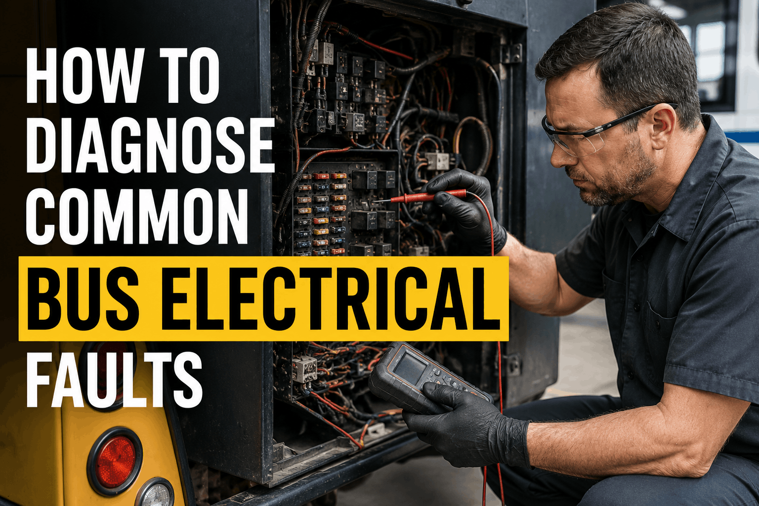
Electrical faults are among the most frustrating and time-consuming issues to diagnose on a bus. A dead battery, flickering lights, intermittent gauge failures, and parasitic draws can take hours or even days to track down—and often lead to unnecessary parts replacement. Yet most electrical faults follow predictable patterns. This guide walks through the six most common bus electrical faults: dead batteries, alternator failures, parasitic draws, ground faults, voltage drops, and intermittent lighting issues. For each fault, you'll find a step-by-step diagnostic procedure, the tools you need, and the specific voltage readings that tell you whether to repair or replace.
Electrical Diagnostics Guide 2026
How to Diagnose Common Bus Electrical Faults
Diagnose common bus electrical faults: dead battery, alternator failure, parasitic draw, ground faults, voltage drops and intermittent lighting issues.
Electrical Faults by Frequency: What Actually Fails
Understanding which electrical components fail most often helps focus diagnostic efforts and preventive maintenance. Data from fleet electrical repair records shows clear patterns:
Battery failures account for 38% of all electrical faults, followed by alternator failures at 24%. Ground faults and parasitic draws make up another 27%. This means almost 90% of electrical issues are in these four categories—a focused diagnostic approach can resolve most electrical problems quickly.
Diagnostic Flowchart: Where to Start
1
Check Battery Voltage
Resting voltage below 12.4V indicates discharged or failing battery. Proceed to load test.
2
Load Test Battery
Below 80% capacity = replace. Above 80% = proceed to charging system test.
3
Test Alternator Output
13.5–14.5V (12V systems) or 27–29V (24V systems) = good. Outside range = alternator or regulator issue.
4
Check for Parasitic Draw
Over 100mA draw = excessive. Identify circuit by pulling fuses one at a time.
5
Inspect Grounds and Connections
Clean to bare metal, torque to spec. Test voltage drop across connections.
The Six Common Faults: Diagnosis and Repair
1. Dead Battery
Symptoms: Slow crank, no start, dim lights. Voltage below 12.0V.
Diagnosis: Load test. CCA below 80% = replace.
Common Causes: Age, sulfation, excessive discharge, failed alternator.
Fix: Replace battery. Test charging system to prevent recurrence.
2. Alternator Failure
Symptoms: Battery warning light, dim lights, dead battery, electrical accessories slow.
Diagnosis: Check output: 13.5–14.5V (12V) or 27–29V (24V). Check AC ripple.
Common Causes: Worn brushes, failed diodes, bearing failure.
Fix: Replace alternator. Inspect belt and tensioner.
3. Parasitic Draw
Symptoms: Battery drains overnight or over weekend. Hard start after sitting.
Diagnosis: Ammeter test between battery and cable. Over 100mA = draw.
Common Causes: Failed relay, stuck switch, faulty module.
Fix: Pull fuses one by one to identify circuit. Repair or replace faulty component.
4. Ground Faults
Symptoms: Intermittent electrical issues, flickering lights, erratic gauges.
Diagnosis: Voltage drop test between ground point and battery negative.
Common Causes: Corrosion, loose connection, broken ground strap.
Fix: Clean to bare metal, tighten to spec. Apply dielectric grease.
5. Voltage Drop
Symptoms: Dim lights, slow accessories, intermittent function.
Diagnosis: Measure voltage drop across circuit. Over 0.5V = excessive resistance.
Common Causes: Corroded connections, undersized cables, damaged wiring.
Fix: Clean connections. Replace damaged wiring. Upgrade cables if needed.
6. Intermittent Lighting
Symptoms: Lights flicker, work sometimes but not others.
Diagnosis: Check ground connections. Test voltage at socket. Inspect wiring.
Common Causes: Loose connections, corroded sockets, broken ground.
Fix: Clean or replace sockets. Repair wiring. Tighten connections.
Diagnostic Tools Required
Multimeter
Essential for voltage, resistance, and continuity testing. Look for CAT III rated for vehicle electrical systems.
Load Tester
Carbon pile or electronic load tester for battery capacity testing. Essential for accurate battery diagnosis.
Ammeter / Clamp Meter
DC clamp meter for parasitic draw testing without disconnecting cables. Safer and faster than series ammeter.
Test Light
Simple, quick verification of voltage presence. Use a low-current LED test light to prevent circuit damage.
Circuit Tester
Power probe or circuit tester for testing circuits under load. Identify voltage drops and poor connections.
Diagnostic Scanner
For reading ECM and module fault codes. Identifies electrical issues that trigger warning lights.
We implemented this electrical diagnostic guide across our 95-bus fleet. In the first year, our average electrical diagnosis time dropped from 2.5 hours to 45 minutes. We reduced unnecessary alternator replacements by 40% because we identified ground faults and voltage drops that were causing charging issues. The step-by-step process helped our technicians systematically diagnose electrical faults instead of guessing and replacing parts.
Digitize Your Electrical Inspection Process
BusCMMS guides technicians through every electrical inspection point—battery testing, alternator output, voltage drop measurement, ground inspection, and parasitic draw testing. Auto-schedule electrical PM intervals based on mileage. Complete audit trail for every electrical component in your fleet.
Bus Electrical Diagnostics FAQs
What is the normal alternator output voltage for a bus?
For 12V bus electrical systems, normal alternator output is 13.5–14.5V at idle and 1,500 RPM. For 24V systems, normal output is 27.0–29.0V. Output below specification indicates alternator or voltage regulator issues. Output above specification can damage batteries and electrical components.
How do I test for a parasitic draw?
Connect an ammeter between the battery negative terminal and cable. Normal parasitic draw is 50–100mA. Draw above 100mA indicates a failed component. Isolate by removing fuses one at a time until the draw drops—the last fuse identifies the circuit with the fault.
What is a voltage drop test?
A voltage drop test measures the voltage loss across a circuit or connection. Acceptable voltage drop is 0.1–0.3V for most circuits. Readings above 0.5V indicate excessive resistance from corroded connections or damaged wiring. Voltage drop testing identifies poor connections that cause intermittent issues.
Why do bus ground connections fail?
Ground connections fail from corrosion, vibration, and age. A poor ground can cause flickering lights, erratic gauges, slow starting, and charging system problems. Regular ground point inspection, cleaning, and torquing prevents these issues. Apply dielectric grease to protect cleaned connections.
What causes intermittent electrical issues?
Intermittent electrical issues are almost always caused by poor connections—corroded terminals, loose grounds, or damaged wiring. Vibration causes intermittent connections that can be impossible to find with static testing. Use voltage drop testing and circuit testing under load to identify intermittent issues.
Can BusCMMS track electrical inspection history?
Yes. BusCMMS tracks battery test results, alternator output readings, voltage drop measurements, ground inspection results, and parasitic draw test results. This creates a complete electrical history for each bus, helping identify recurring issues and predict component failure.
The Bottom Line
Diagnosing bus electrical faults does not have to be time-consuming or frustrating. Most faults follow predictable patterns: battery failures, alternator failures, ground faults, and parasitic draws account for almost 90% of electrical issues. A systematic diagnostic approach—starting with battery testing, then alternator output, then parasitic draw, then grounds—resolves most electrical problems quickly. This guide provides the step-by-step procedures your technicians need to diagnose and repair common bus electrical faults. When combined with BusCMMS digital inspection forms, auto-scheduled PM intervals, and complete electrical history tracking, your electrical maintenance program becomes proactive—catching issues before they cause breakdowns or roadside failures.