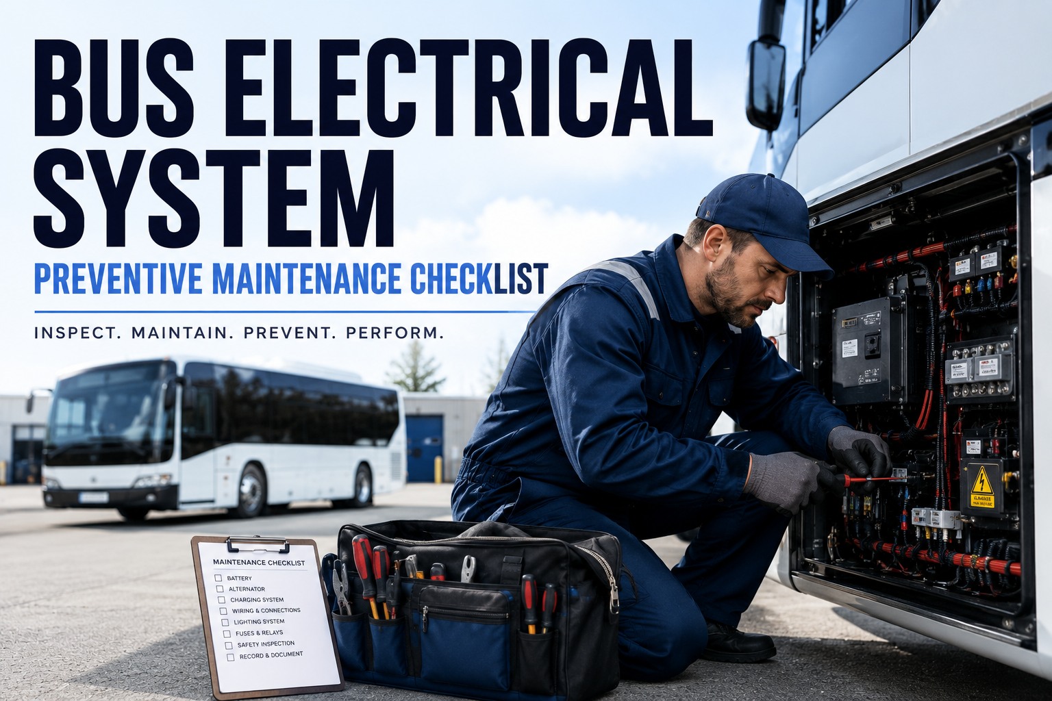
It is 5:47 AM in the yard, cold enough to see your breath, and Bus SB-114 will not crank. The starter clicks but the engine will not turn over. Your driver has a full route of high school kids leaving in 18 minutes. Now your mechanic is out there in the dark with a jump pack, a voltmeter, and a growing suspicion that the alternator has been undercharging that battery for six weeks. Nobody caught it because the pre-trip only confirms the headlights come on -- not what the charging system is actually doing. Electrical failures are the single largest cause of unscheduled bus downtime in most fleets. Almost every one of them was leaving warning signs three to six weeks before the bus refused to start. This guide gives you the free bus electrical system preventive maintenance checklist you can hand to drivers and technicians tomorrow morning -- with the exact diagnostic readings, pass and fail thresholds, and early warning signs that keep alternators, batteries, starters, and safety circuits running through winter without a single cold-crank surprise.
Free Bus Electrical System Preventive Maintenance Checklist
Every test point, expected reading, and warning sign -- ready for tomorrow's shop workflow
- 6Electrical subsystems
- 100+Circuits per bus
- 3-5 yrBattery life target
Why Electrical Failures Are the #1 Reason Buses Miss Routes
Ask any veteran shop foreman what breaks first on a school bus and the answer is not brakes, not transmission, not engine. It is the electrical system. Modern buses run 1-2 miles of wiring and 100+ circuits keeping everything alive: engine controls, safety equipment, HVAC blowers, defrost, wheelchair lifts, DVIR panels, ABS modules, and every warning lamp on every side of the vehicle. Any one of those circuits can pull a bus off the road.
-
#1
Cause of Cold-Crank No-Starts
A weak battery combined with a marginal alternator kills more morning routes than any other failure mode -- especially November through February.
-
3-6
Weeks of Warning Before Failure
Most electrical failures announce themselves slowly. Voltage drift, slower cranking, dim lamps -- all catchable with the right PM schedule.
-
DVIR
Where Paper Checks Fail
Standard pre-trip DVIRs verify lamps light up. They rarely capture voltage drop, charging output, or ground integrity -- the actual diagnostic data.
-
$$$
Cascading Cost of Missed PMs
An undercharging alternator kills a battery. A bad ground burns wiring. One skipped test becomes a multi-part repair three months later.
The good news: every one of these failure modes is visible weeks in advance if you are measuring the right things at the right intervals. The bad news: paper checklists rarely capture the numbers that would tell you. Book a demo to see how BusCMMS captures voltage-drop trends and flags failing systems before they strand a bus.
The 6 Electrical Subsystems Every Bus PM Program Must Cover
A bus electrical system is not one thing. It is six interconnected subsystems that share a battery, a ground plane, and a lot of copper. Any electrical PM checklist has to touch each of them independently -- because a healthy battery does not tell you anything about whether the ground path is corroded, and a working starter says nothing about whether the alternator is actually charging.
-
1. Battery Bank & Grounds
Two 12V batteries in parallel (typical). Terminal condition, resting voltage, load capacity, cable tightness, ground integrity.
-
2. Charging System
Alternator, voltage regulator, drive belt. Output amperage, charging voltage under load, belt tension, case temperature.
-
3. Starting Circuit
Starter motor, solenoid, ignition switch, relays. Cranking amps, engagement crispness, cranking RPM, voltage drop under load.
-
4. Lighting & Safety Circuits
Headlamps, marker lamps, 8-way warning lights, stop arm flashers, crossing gate lights, backup alarm, brake lamps.
-
5. Wiring & Junction Points
Harnesses, connectors, junction blocks, insulation. Visual inspection, voltage drop across critical runs, corrosion at pins.
-
6. Fuses, Relays & Controls
Fuse panel, relay bank, control modules. Continuity, contact condition, correct amperage rating, mounting integrity.
Every one of these subsystems needs its own PM interval and its own diagnostic threshold. A bus-specific CMMS ships with each of them pre-configured. Book a demo to see all 6 subsystems tracked on one dashboard.
The Diagnostic Reading Checklist: Test Points, Ranges & Actions
This is the checklist your technician actually uses. Each card is one test point from one subsystem, with the expected reading, the pass/fail threshold, and the exact action to take if the reading is out of spec. Print these, laminate them, keep them at the bay -- or load them into a digital DVIR so the readings feed straight into a work order when they fail.
Battery Voltage (Resting)
- PASS 12.4-12.7V after sitting 8+ hours
- FAIL Below 12.4V or above 12.9V resting
Alternator Output (Idle + Load)
- PASS 13.8-14.5V engine running, headlights + blower on
- FAIL Below 13.5V under load or above 14.8V any time
Ground Circuit Voltage Drop
- PASS Below 0.2V under load (starter cranking)
- FAIL Above 0.2V -- most electrical gremlins live here
Starter Cranking Voltage
- PASS Above 9.6V while engine cranks
- FAIL Below 9.6V -- weak battery or high-resistance connection
Warning Light Circuit Continuity
- PASS All 4 amber + 4 red lamps flash on activation
- FAIL Any dim, dark, or delayed lamp -- bus does not roll
Fuse Panel + Relay Contact Check
- PASS Every fuse conducts; relays click crisply on trigger
- FAIL Blown fuse, weak relay click, or corrosion on contacts
Those six readings, tracked monthly per bus, give you 90% of the early-warning signal you need. The problem with paper: nobody plots the trend. A voltage that drifted from 12.6V to 12.5V to 12.4V over three months is invisible on paper but obvious in a CMMS. Sign up free and load these 6 diagnostic checks into a digital DVIR.
PM Frequency: What to Test Daily, Monthly, and Annually
Diagnostic tests belong on different cycles. Some run every day (visual and functional). Some run monthly (voltage and continuity). Some run quarterly or annually (deep component analysis). Here is the cadence a well-run electrical PM program follows.
| Test / Component | Daily | Monthly | Quarterly | Annual |
|---|---|---|---|---|
| Warning lamp function (all 8) | ||||
| Headlamps + marker lamps | ||||
| Battery resting voltage | ||||
| Alternator output under load | ||||
| Battery load / capacity test | ||||
| Ground voltage drop | ||||
| Starter cranking amps | ||||
| Wiring harness visual inspection | ||||
| Fuse panel + relay bank |
A generic CMMS makes you build this cadence from scratch. A bus-specific CMMS ships with these intervals pre-configured for school bus, transit, and charter duty cycles -- and lets you tighten them by fleet segment as your MTBF data comes in. Book a demo to see this frequency matrix running live with automated PM triggers.
5 Electrical Warning Signs Drivers and Techs Should Catch Early
Buses talk. They tell you what is failing weeks before it strands them. The trick is training drivers to note the small stuff on the DVIR and having a CMMS that turns those notes into open work orders instead of losing them in a paper stack.
-
01
Slower Cranking Than Last Week
SYMPTOMEngine takes longer to start, especially first thing in the morning.USUALLY MEANSBattery losing capacity or high-resistance connection at the starter cable.ACTIONLoad test the battery + measure voltage drop on the starter feed. -
02
Dashboard Voltmeter Dropping at Idle
SYMPTOMVoltmeter reads normal at speed but drifts down at stops or in reverse.USUALLY MEANSAlternator marginal at low RPM, loose belt, or worn diode.ACTIONCheck belt tension; test alternator output at idle with load. -
03
Dim or Flickering Warning Lamps
SYMPTOMOne or more of the 8-way warning lamps looks noticeably dimmer than the others.USUALLY MEANSBad ground at the lamp socket, corrosion, or a bulb near end of life.ACTIONSwap the bulb first; if unchanged, clean the socket and inspect the ground path. -
04
Repeated Fuse Blowing on the Same Circuit
SYMPTOMSame fuse pops within days or weeks of being replaced.USUALLY MEANSShort in the circuit, chafed wiring, or a failing component drawing excess current.ACTIONTrace the circuit; check for chafing at hinge points and behind panels. -
05
Battery Terminal Corrosion (White or Green Powder)
SYMPTOMFuzzy white/green deposit on the positive or negative battery terminal.USUALLY MEANSLoose connection allowing outgassing, or an aging battery venting.ACTIONClean with baking soda solution, retorque terminals, apply protectant.
Any one of these on the DVIR should trigger a work order automatically. In a paper system, they usually do not. Book a demo to see how failed DVIR items become open electrical work orders in real time.
The Battery-Alternator-Starter Loop: One Loop, One Set of Failures
Almost every electrical no-start on a bus comes down to a broken link in the same four-node loop. Battery gives up current to crank the starter. Starter turns the engine. Engine drives the alternator. Alternator recharges the battery. Break any node and the loop collapses within a few days.
Battery
Stores 12V, delivers cranking current, absorbs charge from alternator.
Starter
Draws 200-800 amps briefly to crank the engine; solenoid engages the flywheel.
Engine + Belt
Once running, drives the alternator via serpentine belt. Belt tension matters.
Alternator
Produces 13.8-14.5V, replenishes battery and powers accessories while running.
The loop's weakest link decides the fleet's cold-morning survival. A battery might be fine, but if the alternator only produces 13.2V under load, the battery slowly discharges over a week. A CMMS that trends charging voltage per bus catches that drift before it becomes a no-start. Book a demo to see per-bus voltage-drift trending on real fleet data.
Paper Checklists vs. BusCMMS Electrical PM: The Real Difference
A paper checklist tells you what happened once. A CMMS built for buses tells you what is happening across the fleet, per bus, week over week. On an electrical system where failures announce themselves gradually, that difference decides whether you catch the fade or wait for the strand.
BusCMMS reports that fleets using its electrical PM workflow cut electrical-caused road calls by 50-70% within the first 6 months, based on customer-reported outcomes. On a 50-bus fleet, that is 30-50 fewer road calls per year -- and 30-50 fewer angry parent phone calls. Book a demo to see the electrical PM workflow on your actual fleet size.
The Bottom Line on Bus Electrical PM
Use the checklist on this page as your electrical PM starting point. Every bus in your fleet should have those six diagnostic readings taken at the frequency shown, with the results tracked over time. Paper works for one bus. It falls apart at ten. If your fleet is bigger than that, upgrade to a CMMS built for bus electrical PM so the readings, work orders, and audit records take care of themselves.
What is a bus electrical system preventive maintenance checklist?
It is a structured list of tests and inspections performed on the bus electrical system at defined intervals to catch degradation before it causes a road failure. A complete checklist covers six subsystems: battery bank and grounds, charging system (alternator and regulator), starting circuit, lighting and safety circuits, wiring and junction points, and fuses/relays/controls. Each test point has an expected reading, a pass/fail threshold, and a defined action if the reading is out of spec.
What voltage should a healthy bus battery read?
A healthy 12V bus battery reads 12.4-12.7V at rest (after 8+ hours without charging). Above 12.9V resting suggests overcharging. Under load (starter cranking), voltage should stay above 9.6V. When the engine is running, the alternator should raise system voltage to 13.8-14.5V under load. Any reading outside these ranges points to either a battery nearing end of life or a problem in the charging system.
How often should a bus electrical system be inspected?
Daily driver DVIRs should confirm all warning lamps, headlamps, and safety circuits activate normally. Monthly PM should include battery resting voltage and alternator output under load. Quarterly PM should include battery load/capacity testing, ground voltage drop tests, and starter cranking amps. Annual PM should include full wiring harness visual inspection, fuse panel and relay bank continuity checks, and a complete electrical audit. Seasonal (pre-winter) testing is essential for cold-crank reliability.
What are the most common bus electrical failures?
The most common failure modes are: battery aging (typically 3-5 year life), alternator undercharging (marginal output at idle), high-resistance ground connections (voltage drop above 0.2V), corroded battery terminals, chafed wiring at hinge points causing shorts, and worn starter solenoids showing slow engagement. All six are catchable weeks in advance by tracking the diagnostic readings in this guide monthly per bus and trending the results in a CMMS.
Can BusCMMS help track bus electrical preventive maintenance?
Yes. BusCMMS ships pre-configured with electrical PM templates for school bus, transit, and charter fleets. Drivers run pre-trip electrical checks from a digital DVIR that logs voltage readings, warning lamp status, and warning signs. Failed checks automatically create work orders with parts reserved from inventory. Voltage trends are graphed per bus so drift becomes visible weeks before failure. Battery age, alternator lifecycle, and starter replacement history are tracked per VIN. Audit-ready reports export in one click for FMCSA and state DOT reviews.